

|
W0JEC’s Projects |
|
Contents |
|
Building the Picaxe Microcontroller Board
Now that you have the software installed for remote radio and rotator control, audio pathway between your remote computer and radio, and virtual private network between computers over the internet, it’s time to build and connect the microcontroller circuit board that will control everything else you need for HF remote operation.
The schematic for the circuit board you will build can be downloaded from the Download page and is shown here. The circuit board project can be built for under $30; the parts can be obtained from the sources indicated on the schematic page or from your junk box. I used the 5VDC kit from PH Anderson for powering the Picaxe chip and powered the entire board with 12VDC from my station power supply. The project fits easily onto a multipurpose PC board from Radio shack; use 18 pin dip sockets for the two chips and point to point wiring. Board layout is your choice and a plastic project box from Radio Shack can be used for mounting the DB9 cable connector, the jack for 12VDC power, RCA jacks for the relays, and the 1/8 inch stereo jack for the DST-6. If you are not experienced with building circuit boards, just remember to use a 15-20 watt soldering iron and avoid solder bridges between the tiny pins on the dip sockets.
The Picaxe Circuit
The Picaxe chip connects to the home computer using a serial port and connects to the LDG DTS-6 (or DTS-4 if you have one) using TTL signals over a 1/8 inch stereo cable. It also connects to up to 8 12VDC relays to control other station accessories. The circuit uses two power sources; a 12VDC board supply from a 12VDC external supply and an internal 5VDC regulated supply for the Picaxe chip itself on the board. The Picaxe and Darlington chips are mounted on 18 pin dip sockets. Since the Picaxe chip cannot sink enough amperage to control 8 12VDC relays, the relays are connected through a ULN2803A Darlington array chip which is in turn controlled by the Picaxe chip. The 12VDC relays shown on the schematic are not located on the project board itself; they are located wherever you want them and wired to the Darlington array chip through RCA jacks or any other means of your choice. The station control relay numbers match the station control numbers shown on the software configuration screen.
For my station control setup, I use a relay inside my Hygain Rotator Control to turn 120VAC on and off, a relay to turn on and off 12VDC power for my SGC antenna coupler, a relay to cycle my SGC coupler reset, and a relay to manage the switching between my Kenwood TS-570S and Icom IC-718 rigs. Note: if you do not have a DST-4/6 antenna switch, additional 12VDC relays could be used for antenna switching as shown on a separate schematic that can be downloaded from the Download page.
Controlling the Picaxe Microcontroller
For this Picaxe microcontroller project, I control the chip from the computer over the serial port connection to the circuit board. The folks who sell the chip very kindly furnish free programming software and easy to follow instructions for writing and loading the software into the chip. The chip can then be connected to a computer and software running on the computer can control the chip functions. I have written the chip command file for using the chip to control the DST-4/6 antenna switch and for turning on and off up to eight relays. After you build the project board and install the Picaxe chip, you must program the chip using the free Picaxe programming software supplied by Revolution Education to load the command file into the chip. The programming software includes a detailed help section explaining how to connect to and program the chip from your computer and I recommend that you review this information carefully before proceeding, but the following is a summary of the steps needed to program the chip: · Download and install the Picaxe programming software. · The W0JECRemoteStaContDST.bas command file is included in the "W0JEC Station-DTS Control" zip file on the Download page. Save this file to a folder on your home computer. · Start the Picaxe Programming software; click on Open and browse to the folder where you have placed the Picaxe command file. Select the file to open it in the editor. · Once this file is opened in the editor, click on Options to select the serial port the Picaxe project board is connected to. · To download the file into the Picaxe chip requires the following hard reset and download procedure: disconnect the power to the project board, click on Program, reconnect power to the project board. The editor program will now reset the chip and download the command file to the chip. · Once the file has been successfully downloaded to the chip, you may close the editor. · The Picaxe chip is now programmed and ready to be operated by the VB program "W0JEC Station-DTS Control” which is described on the Station Control page of this website.
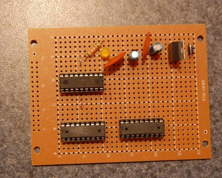
The photo below shows the project board with power supply, Picaxe chip and two Darlington chips. Only one chip is used for this circuit but two are required for the alternate circuit described for those who do not own a DST –4/6 antenna switch. Point-to-point wiring must be added to complete the board.
|